
|
|
1.IntroductionThe cloning and subsequent bioengineering of light-driven channels (e.g., channelrhodopsins) or pumps (e.g., halorhodopsin and archaerhodopsins) has opened a new avenue in the field of optogenetics.1 Optogenetics is a powerful method in neuroscience because these opsins can be expressed in specific subsets of neurons by genetic manipulation, allowing dynamic modulation of the discharge of these cells by light.2 In animal experiments, the effectiveness of brain manipulation is ultimately assessed by an animal’s behavior. Because most rodent behavioral experiments assume free movement of the animals, a light delivery method that does not compromise their movement is desired. One approach is to have a remote light source and deliver the light by an optical fiber. In this approach, the animal’s skull is implanted with an optical interface (e.g., cranial window or optical fiber directed to an area of interest) that can be coupled to the optical fiber.3–5 While this approach is practical and widely used, it has some shortcomings. First, the animals need to move in a trajectory that allows access of the optical fiber, so movement through a ring or tube will be problematic. Second, a rotary joint is required to avoid contortion caused by the animal’s rotational movement. Third, it is difficult to house multiple wired animals in an experimental arena, which is often required to test social aspects of animal behavior. An alternative approach is to have a light source embedded in a head-implantable device that is controlled by wireless remote control.6,7 To this end, we have designed a simple head-mountable wireless light-emitting diode (LED) illumination device that switches on during reception of 38-kHz near-infrared (IR, ) photopulses.6 This first-generation device has room for improvement, including downsizing, multiple output LEDs, programmable output signal, and multicode reception. Here we introduce the second-generation device that implements these enhancements. The advanced system is suitable for optogenetic stimulation for behavioral experiments in complex environments with multiple animals. 2.Materials and Methods2.1.IR TransmitterThe IR transmitter (Fig. 1) is composed of four Bayonet Neill-Concelman (BNC) input ports that accept external transistor-transistor-logic (TTL) triggers (Fig. 1, Ch.1 to Ch.4), a microcontroller (PIC16F628A-I/P, Microchip Technology Inc., Chandler, Arizona), and analog switches (n-Kanal MOSFET, 2N7000, Fairchild Semiconductor Co., San Jose, California) to control the output of the IR LEDs (940 nm; QED234, Fairchild). In addition to the transmitting IR LEDs embedded in the box (Fig. 1, internal IR LEDs), a pair of receptacles is provided for connection of external IR LEDs (Fig. 1, receptacles for external IR LEDs). The external or internal IR LEDs are selected by a mechanical switch. Using external IR LEDs, we can provide IR photopulses to an experimental apparatus at any angle and bring IR LEDs into a behavior testing room and soundproof isolation box [Fig. 1(b)]. The microcontroller was programmed to generate IR photopulses using a PICkit2 compatible programming board (AE-PICPGM USB, Akizuki Denshi Tsusho Co., Ltd., Tokyo, Japan). Fig. 1Infrared (IR) transmitter for wireless optogenetic stimulation. (a) Circuit diagram of the IR transmitter. (b) Photograph of the IR transmitter connected to six external IR light-emitting diodes (LEDs). Upon reception of transistor-transistor-logic (TTL) trigger signals through the BNC ports (Ch.1 to Ch.4), the microcontroller (PIC16F628A) generates input-channel-specific pulse patterns to the output IR LEDs. Internal and external IR LED output is selected by a mechanical switch. Scale bar, 1 cm. 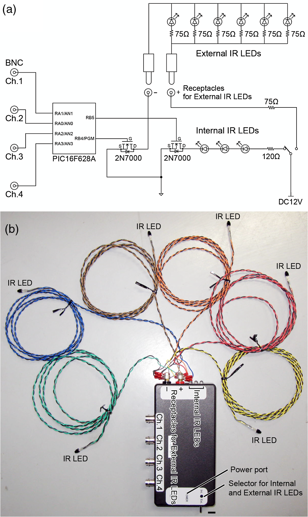 The IR transmitter has four channels for an external TTL input (Fig. 1, Ch.1 to Ch.4). When the channel is activated, the microcontroller generates a train of pulses, which is based on the NEC format for IR remote controllers ( http://www.vishay.com/docs/80071/dataform.pdf). Briefly, the IR transmission code consists of a leader code (9 ms On followed by 4.5 ms Off signal), an 8-bit binary code (e.g., Ch.3, 00001111; 0 is coded 0.55 ms On followed by 0.55 ms Off, 1 is coded by 0.55 ms On followed by 1.65 ms Off), and a stop bit (0.55 ms On followed by 0.55 ms Off) (Fig. 2). Each channel of the IR transmitter is identified with a unique 8-bit binary code (e.g., Ch.1, 00001101; Ch.2, 00001110; Ch.3, 00001111; Ch.4, 00011100). The 256 patterns of the 8-bit binary code (00000000 to 11111111) are available for each channel. The 8-bit binary code of each channel is defined by the program installed in the microcontroller of the IR transmitter. Multiple IR transmitters can be used without crosstalk between the channels by assigning a unique 8-bit binary code to each channel (e.g., Ch.1, 00001101; Ch.2, 00001110; Ch.3, 00001111; Ch.4, 00011100; Ch.5, 00011101; Ch.6, 00011110; Ch.7, 00011111; Ch.8, 00000100). The IR transmission code is modulated at a carrier frequency of 38 kHz using amplitude shift keying to resist influence from environmental IR noise (Fig. 2). Furthermore, a carrier frequency of 30 or 56 kHz can be used to realize multiband IR transmission. The IR transmitter is powered by an ac adapter that provides dc 12 V. Fig. 2Schematic diagram of the wireless LED-stimulating system. When a TTL trigger signal is presented to a channel on the IR transmitter (e.g., Ch.3), the microcontroller generates a train of pulses composed of a leader code, unique eight-bit binary code for the channel (e.g., Ch.3, 00001111), and stop bit. The train of pulses is encoded with amplitude shift keying at a carrier frequency of 38 kHz and IR transmission is made accordingly. The transmitted IR photopulses are received and decoded by the IR receiver on the LED stimulator. The decoded signal is processed into 8-bit binary code by the microcontroller on the LED stimulator. Next, the microcontroller reads out an LED number (LED1 to 3) and pulse pattern, including duration, frequency, and pulse width, according to the 8-bit binary code. Finally, the LED generates photopulses according to the pulse pattern. The pulse pattern of each LED can be defined by specifying the duration (), frequency (), and pulse width () in the program installed in the microcontroller of the LED stimulator. 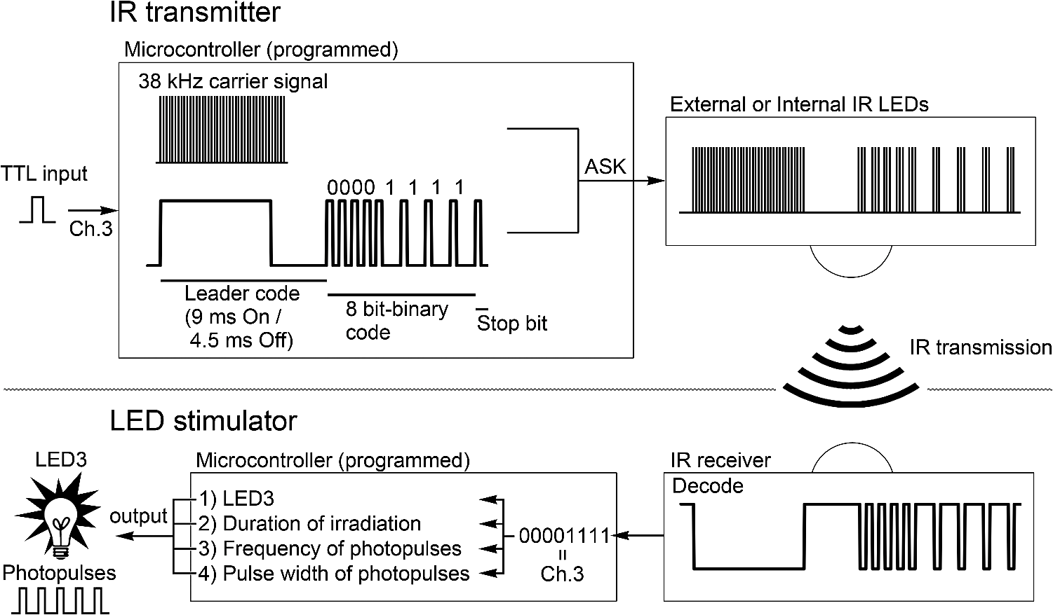 2.2.LED StimulatorThe LED stimulator is built on a double-sided printed circuit board (PCB). A detailed circuit diagram is presented in Fig. 3(a). The power is supplied by a lightweight lithium polymer battery (output: 3.7 V, 10 mAh; size: ; mass: 0.52 g; Guangzhou Fullriver Battery Ltd., Guangzhou, China), which is converted to dc 5 V by a boost converter (TPS61222, Texas Instruments Inc., Dallas, Texas). The front side accommodates an IR receiver module for a carrier frequency of 38 kHz (RPM7138-R, Rohm Co., Ltd., Kyoto, Japan), a microcontroller (PIC12F683-I/SN, Microchip Technology), a programming port, and a socket for a battery [Fig. 3(b)]. IR receivers for carrier frequencies of 30 kHz (TSOP4830, Vishay Intertechnology Inc., Malvern, Pennsylvania) and 56 kHz (TSOP4856, Vishay Intertechnology) are also used for multiband IR reception. The backside of the PCB is used to mount the boost converter and receptacles (R861-83-050-10-001, Tokiwa, Tokyo, Japan) for three output LEDs [Fig. 3(c), LED1 to LED3]. The receptacles are also used to attach the LED stimulator to implanted LEDs [e.g., Fig. 4(d)]. Small blue LEDs (, ; LP-1608H183BC, LED-Paradise, Saitama, Japan) were used to activate channelrhodopsin-2 (ChR2). We used two different LED configurations. One had three small LEDs [Fig. 3(d), LED1 to LED3] attached to plugs [R860-10-050-10-001, Tokiwa; Fig. 3(d), arrowhead]. The other had two small LEDs [Fig. 4(c), right LED and left LED] attached to plugs [Fig. 4(c), arrowhead] and connected to LED1 and LED2 of the LED stimulator through an adaptor [Fig. 4(d)]. The supply of current to each LED is limited to 20 mA by a resistor [100 Ω, Fig. 3(a)]. The output power of the LED was measured by an optical power and energy meter (PM100D, Thorlabs Japan Inc., Tokyo, Japan). The height and mass of the LED stimulator including the battery (10 mAh) were 10 mm and 2.4 g, respectively. Fig. 3Head-mountable LED stimulator for wireless optogenetic stimulation. (a) Circuit diagram of LED stimulator. Electric power (5 V) was generated from a 3.5-V battery by a boost converter. (b) Photograph of the LED stimulator connected to a battery (front side). The LED stimulator has a port for programming, through which a program is transferred into the microcontroller. (c) The backside of the LED stimulator. There are three receptacles for LEDs (LED1 to LED3). (d) Top view of a Thy1-ChR2-YFP mouse with an implant of three small LEDs (LED1 to LED3). The LED implant is covered with acrylic dental resin, and a plug connector (indicated by an arrowhead) serves as the interface between the LEDs and LED stimulator. The inset shows the side view of the plug connector. Scale bar, 1 cm. 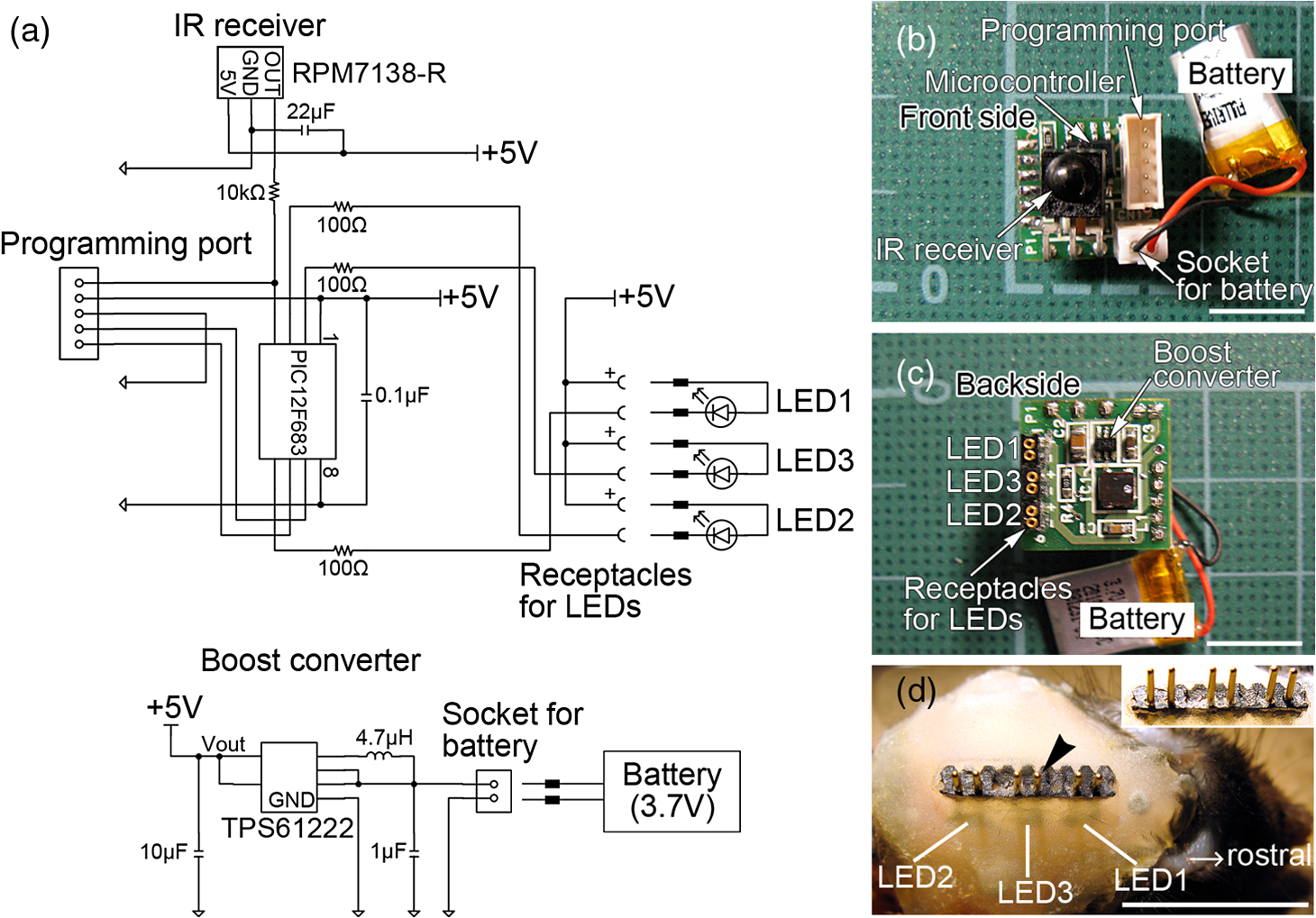 Fig. 4Control of the moving direction of a free-moving Thy1-ChR2-YFP mouse by an LED stimulator. (a) Time-lapse images of a free-moving Thy1-ChR2-YFP mouse during a wireless photostimulation session. The right aM1 was stimulated during the time intervals from 1 to 3 and 7 to 9 s. The left aM1 was stimulated during the time interval from 4 to 6 s. Red arrows indicate the tail-to-head directions just before LED stimulation at 0.7, 3.7, and 6.7 s. Green arrows indicate the head direction of the animal in respective frames. (b) The trajectory of the animal visualized by merging all frames. (c) Top view of a Thy1-ChR2-YFP mouse head with mounted LED system. The LEDs (right LED and left LED) were fixed over the anterior M1 motor cortices of the right and left hemispheres. LEDs attached with a plug connector (arrowhead) were fixed on the skull with acrylic dental resin. The skull was not thinned. (d) Photograph of the same mouse with the LED stimulator mounted on its head. Scale bar, 1 cm. 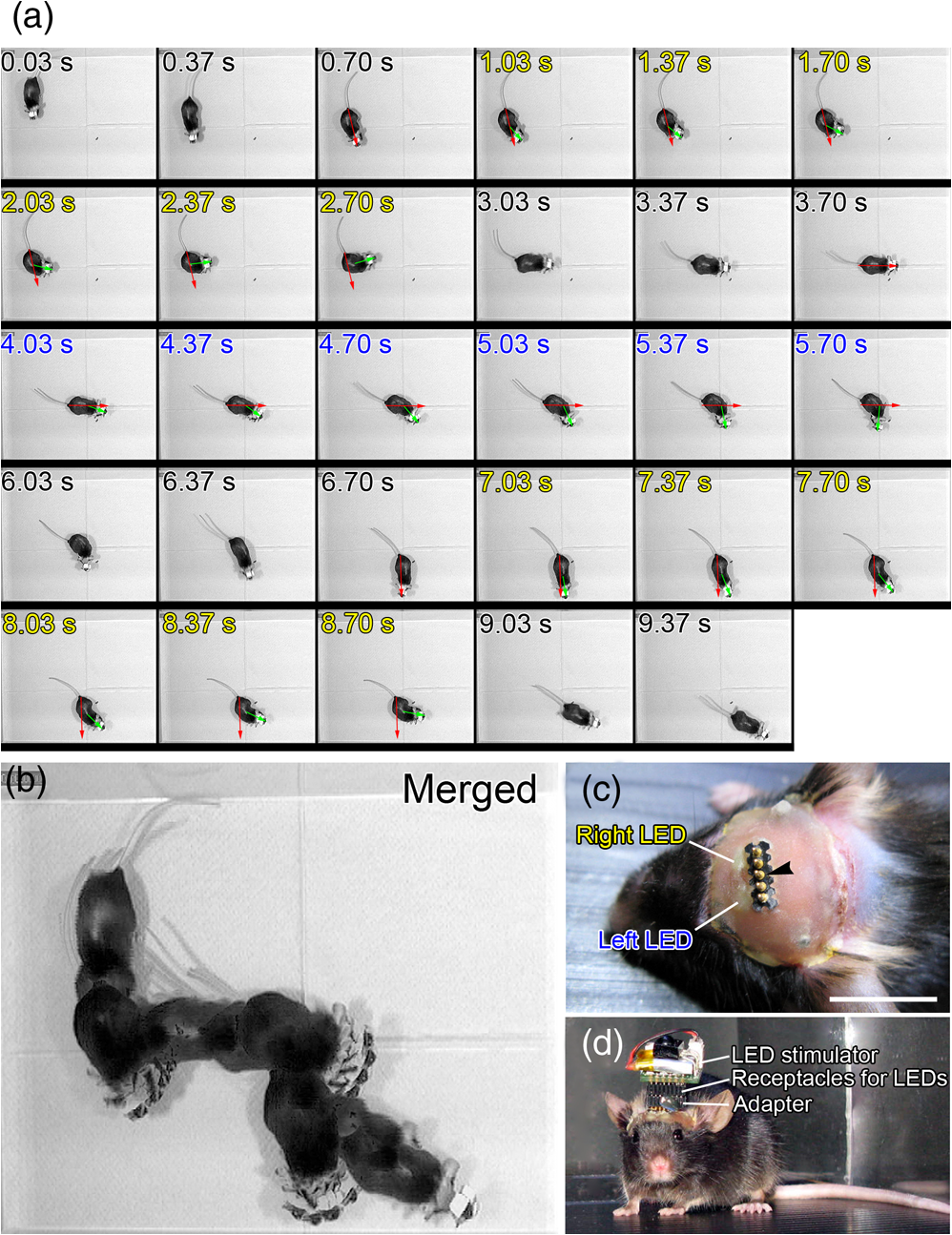 The IR receiver on the LED stimulator decodes the IR-transmission code generated by the IR transmitter into a TTL logic pattern (Fig. 2). The logic pattern is processed into 8-bit binary code by the microcontroller on the LED stimulator. The microcontroller is programmed to identify four patterns of the 8-bit binary codes that are chosen from the 256 patterns of the 8-bit binary codes. The four patterns of the 8-bit binary codes are usually identical to the channel codes of the IR transmitter. The microcontroller is programmed to assign the four patterns of the 8-bit binary codes to each LED of the LED stimulator (e.g., 00001101=Ch.1=LED1; 00001110=Ch.2=LED2; 00001111=Ch.3=LED3; 00011100=Ch.4=LED1 and LED2). According to each 8-bit binary code, the microcontroller is programmed to read out a pulse pattern, including duration, frequency, and pulse width, and generate the pulse pattern to drive the assigned LED (Fig. 2). The pulse pattern of each LED can be flexibly defined by specifying the duration (), frequency (), and pulse width () (Fig. 5) in the program installed in the microcontroller of the LED stimulator. By assigning four patterns out of 256 8-bit binary codes to each LED stimulator, we can individually use multiple LED stimulators (up to 64 devices) without crosstalk (Video 2). By default, the microcontroller activates LED1 by Ch.1/Ch.5 signal reception, LED2 by Ch.2/Ch.6, LED3 by Ch.3/Ch.7, and both LED1 and LED2 by Ch.4/Ch.8. The on-board microcontroller code was developed in assembly language using a PC, and the machine code was transferred using a custom-made cable connected to a PIC-programming board (AE-PICPGM USB). Fig. 5Verification of LED photopulses. (a) Circuit diagram for recording the LED photopulses. The intensity of LED photopulses was converted into voltage variation (Vout) using a phototransistor (NJL7502L, New Japan Radio Co., Ltd., Tokyo, Japan). Vout was digitized at 250 kHz by an oscilloscope (TDS2014B, Tektronix, Tokyo, Japan). (b) LED photopulses from the LED stimulator. The LED stimulator generated 1-ms photopulses at 500 Hz. 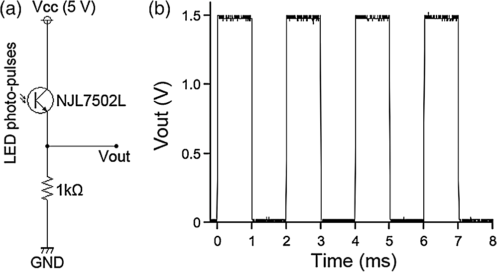 2.3.Animal PreparationThy1-ChR2-YFP transgenic mice that express ChR2 fused to yellow fluorescent protein (YFP) under the control of the Thy1.2 promoter8,9 were housed in a controlled animal facility with a 12-h light/dark cycle. Adult transgenic mice (3 to 10 months old) were used in all experiments. All animal experiments were performed in compliance with the relevant laws and institutional guidelines and were approved by the RIKEN Animal Committee. 2.4.Surgery to Mount the LED StimulatorThy1-ChR2-YFP transgenic mice () were anesthetized with an intraperitoneal injection of sodium pentobarbital ( body weight) and settled in a stereotaxic instrument (SRS-A, Narishige, Tokyo, Japan). Lidocaine hydrochloride solution (AstraZeneca K.K., Osaka, Japan) was injected into the scalp to provide local anesthesia. The skull was exposed, cleaned with 70% ethanol, and three small stainless-steel screws (0.5 mm in diameter) were attached to the skull as anchors. The skull was not thinned. After the small LEDs with connected plugs were placed on the target areas, the small LEDs, skull, and screws were completely covered with clear acrylic dental resin (UNIFAST III, GC Co., Tokyo, Japan), leaving the plugs exposed for connection to an LED stimulator. To photostimulate individual regions, LED1, LED2, and LED3 were fixed over the anterior M1 motor area [aM1, anterior-posterior from bregma (AP): 2 mm, medial-lateral from bregma (ML): 1 mm], the mediolateral V2 visual area (mlV2, AP: , ML: 1 mm), and the posterior M1 motor area and S1 somatosensory area (pM1/S1, AP: , ML: 1 mm) of the right hemisphere, respectively [Fig. 3(d)]. For bilateral motor control experiments, small LEDs were fixed over aM1 of both hemispheres [Fig. 4(c), right LED and left LED]. The animals were allowed to recover for at least 3 days before mounting the LED stimulator for optogenetic experiments. 2.5.ElectromyographyIn two experiments, the upper forelimb muscle movement of the mice was monitored by electromyography (EMG) as described previously.6,10 Mice were anesthetized with an intraperitoneal injection of a ketamine cocktail (ketamine , xylazine ). An LED stimulator was programmed to generate a 50-ms photopulse and mounted on the right side of aM1 [Fig. 7(a), LED1]. EMG activity was amplified () and bandpass filtered (100 Hz to 3 kHz) using a Lynx-8 amplifier (Neuralynx, Bozeman, Montana) and digitized at 10 kHz using customized software written in LabView (National Instruments Japan Co., Tokyo, Japan). Data were analyzed using MATLAB® software (MathWorks, Natick, Massachusetts). 2.6.Recording the Movements of MiceOperated Thy1-ChR2-YFP mice () were individually put in a soundproof isolation box (O’Hara & Co., Ltd., Tokyo, Japan) and their activity was recorded with a video tracking system (ANY-maze, Stoelting Co., Wood Dale, Illinois) at 30 frames per second. The LED stimulator was programmed to generate 50-ms photopulses for 2 s at 10 Hz. The 2-s pulse train to the right or left LED was presented in alternating fashion at 1-s intervals [Fig. 4(a); Video 1]. A montage photograph was generated from video images with the Make Montage function of ImageJ software (NIH, Bethesda, Maryland). Video 1Controlling the movement of a free-moving Thy1-ChR2-YFP mouse by an LED stimulator. The mouse had the LED stimulator mounted on its head. The LED stimulator photostimulated the aM1 motor cortices three times with the order of right, left, and right hemispheres. When aM1 on the left and right hemispheres was transcranially stimulated by the LED stimulator, the mouse changed its moving direction to the right and left, respectively. (QuickTime, 0.6 MB) [URL: http://dx.doi.org/10.1117/1.NPh.1.1.011002.1]. 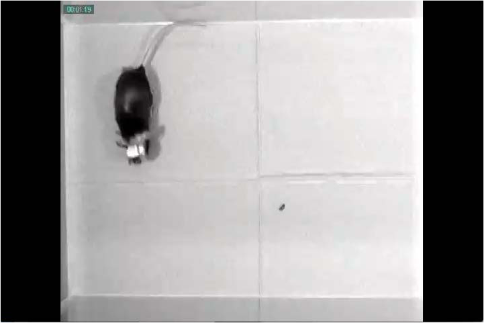 2.7.HistologyThe animals were fixed with an intracardiac perfusion of 4% paraformaldehyde in 0.1 M phosphate buffer (pH 7.4) under diethyl ether anesthesia after the behavior experiments. To examine the positions of the implanted LEDs, transverse brain sections were obtained in a cryostat (Leica CM1850, Solms, Germany) and subsequently stained with cresyl violet (Merck Ltd., Tokyo, Japan). 2.8.Analysis of Light IntensityAfter fixation of the animals as described in Sec. 2.7, the parietal bones of adult (six months old) and young adult (seven weeks old) mice were collected. The parietal bones were fixed overnight, washed with phosphate-buffered saline (–), and dried. The output power of a small LED attached to the LED stimulator was measured directly and through the parietal bones by an optical power and energy meter (PM100D, Thorlabs Japan Inc.). White paper that was illuminated by the small LED directly and through the parietal bone of the adult mouse (6 months old) was digitized with a PowerShot G7 camera (shutter speed ; F8.0; Canon, Tokyo, Japan). The contour of light intensity in the images was calculated with code written in MATLAB®. 2.9.Small LED Coupled to an Optical FiberBoth ends of a plastic optical fiber (POF; 1 mm in diameter; ESKA, Mitsubishi Rayon Co., Ltd., Tokyo, Japan) were heated and softened, and then pushed against a mirrored surface to flatten the ends. One end of the POF was attached to the center of a small LED (470 nm; LP-1608H183BC, LED-Paradise) by soldering with polyurethane-coated copper wire (0.2 mm in diameter; Sunco Co., Kyoto, Japan) and bonding to the small LED with epoxy adhesive. 2.10.Small LED Enclosed in a Glass PipetteA small LED (470 nm; LP-1608H183BC, LED-Paradise) was soldered with polyurethane-coated copper wire (0.2 mm in diameter; Sunco Co.). The wired small LED was inserted into a glass pipette (outside diameter: 1.5 mm, internal diameter: 0.86 mm; Warner Instruments, LLC, Hamden, Connecticut). The tip of the glass pipette was closed by heating before insertion of the LED. 3.Results3.1.Description of the Wireless LED-Stimulating SystemWe developed a wireless LED-stimulating system for optogenetic molecules. This system was composed of three devices: an IR transmitter (Fig. 1), LED stimulator [Figs. 3(a) to 3(c)], and small LEDs attached to plugs [Figs. 3(d) and 4(c)]. The LED stimulator was connected via a mechanical connection to the plugs of implanted small LEDs [see Fig. 4(d)]. The LED stimulator generated photopulses to control a localized brain region of a freely moving Thy1-ChR2-YFP transgenic mouse. IR pulses from the IR transmitter reached the LED stimulator from distances as far as 15 m. The illuminating angle of the internal IR LEDs was at a distance of 10 cm from the internal LEDs, but it was reduced to 69 deg at a distance of 2 m from the internal LEDs. Therefore, the IR transmission is directional. If there is no obstruction of IR transmission in the experimental field (e.g., an open field), the internal IR LEDs covered the whole area within a 1.37-m radius from a distance of 2 m. If there are objects in the experimental field (e.g., running wheel, nest, dark box, maze, or apparatus used in the three-chamber social test), they obstruct IR signaling between the IR transmitter and LED stimulator. The multiple IR LEDs overcome this problem because they can be arranged to transmit IR signals from any angle, at all corners of a maze, and to the inside of an object in the experimental field. In addition, IR signals generated by the multiple IR LEDs do not interfere with each other. The head-mounted LED stimulator [Figs. 3(a) to 3(c)] is designed to be compact so that it does not compromise the free movement of the mouse. The capacity of the battery on the LED stimulator limited the period of each experiment. The standby time of the LED stimulator was for a 10-mAh battery. The driving time of the LED stimulator with a 10-mAh battery was 67 min if it generated sequential photopulses (50-ms pulses at 10 Hz for 2-s duration at 5-s intervals). For a longer experimental period, a battery with higher capacity is needed, but this comes at the expense of heavier weight (10 mAh: 0.52 g; 20 mAh, 1.3 g). The stand-by time of the LED stimulator was for a 20-mAh battery. The driving time of the LED stimulator with a 20-mAh battery was if it generated sequential photopulses (50-ms pulses at 10 Hz for 2-s duration at 5-s intervals). Using the LED stimulator, we achieved a light intensity level of per small LED at 20 mA. The light intensity of a smaller LED (, APHHS1005QBC/D, Kingbright Electronic Co., Ltd., Taipei, Taiwan) was also tested. This mini-LED generated of blue light at 20 mA. Because action potentials in ChR2-expressing neurons can be evoked by of blue light,11 the light intensity of the small LEDs was sufficient to activate ChR2. Further increases in light intensity would be achieved by decreasing the current limiting resistance. To measure the power change of an LED stimulator with a 10-mAh battery, we let an LED stimulator generate photopulses (50-ms pulses at 10 Hz for 2-s duration at 5-s intervals) for 30 min. The light intensity of the LED stimulator was before the test, and it increased to after the test, possibly because the resistance of the semiconductor (e.g., LED) decreased as its temperature increased. To examine the decrease of light intensity through the mouse skull, we measured the light intensity of the light transmitted through the parietal bones of adult (6 months old) and young adult (7 weeks old) mice. The light intensity of the LED output [; Fig. 6(a)] was decreased by 51% [; Fig. 6(b)] by passing through the parietal bone of the older adult mouse. About 69% () of the LED output was transmitted through the parietal bone of the younger adult mouse (data not shown) because the parietal bone of the younger mouse was thinner than that of the older one. Furthermore, the distribution of light intensity of the direct LED light [Fig. 6(a)] and transmitted light through the parietal bone of an adult mouse [Fig. 6(b)] were calculated. The area showing light intensity of is smaller in the distribution of light intensity of the transmitted light than in that of the direct LED light (Fig. 6). Accordingly, the transmitted light appears to photoactivate ChR2-expressing neurons in the local area. Fig. 6Distribution of light intensity through the skull of an adult mouse (6 months old). (a) A small LED (LED) connected to the LED stimulator directly illuminates a piece of white paper, and the distribution of light intensity () is indicated by the colored lines. In this case, the highest light intensity of the small LED was . (b) The same LED as in (a) illuminates a piece of white paper through the parietal bone (skull) of the adult mouse. The distribution of light intensity () is indicated by the colored lines. The highest light intensity through the parietal bone was . Scale bar, 5 mm. 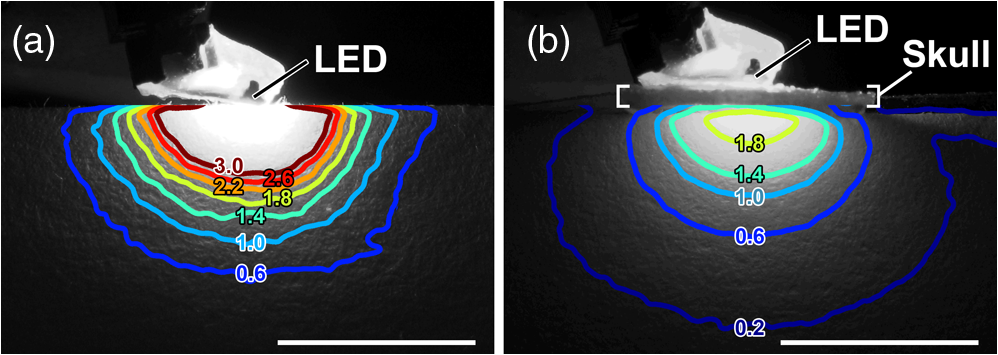 3.2.LED Stimulator-Controlled Movement of Thy1-ChR2-YFP Transgenic MiceTo evaluate the effectiveness of wireless optogenetic stimulation using the LED stimulator, a Thy1-ChR2-YFP mouse was anesthetized and EMG was recorded from the muscle of the left upper forelimb (Fig. 7). When the LED stimulator stimulated aM1 of the right hemisphere [Fig. 7(a)] by a 50-ms photopulse [Fig. 7(b), blue line], the muscles around the left neck and upper forelimb contracted once and a clear EMG response was observed during the 50-ms photopulse [Fig. 7(b)]. In this case, the latent time of EMG reaction to the photostimulation was 14 ms. The LED stimulator took 27.2 ms to start generating LED photopulses after the TTL trigger input into the IR transmitter [Fig. 7(b), arrow]. Fig. 7The LED stimulator evoked a muscle twitch of the upper forelimb by photostimulation of the anterior primary motor cortex (aM1) of a Thy1-ChR2-YFP transgenic mouse. (a) Transverse section of the Thy1-ChR2-YFP brain at the location of LED1 on the skull. Note that no physical damage or cell death is observed at the photostimulation location. (b) Typical electromyogram (EMG) of the contralateral upper forelimb muscle upon photostimulation of aM1. Photostimulation timing to aM1 is indicated by the blue line. The arrow indicates the time when the TTL trigger was activated to the IR transmitter. The LED stimulator generated a photopulse 27.2 ms after the TTL trigger. Scale bar, 1 mm. 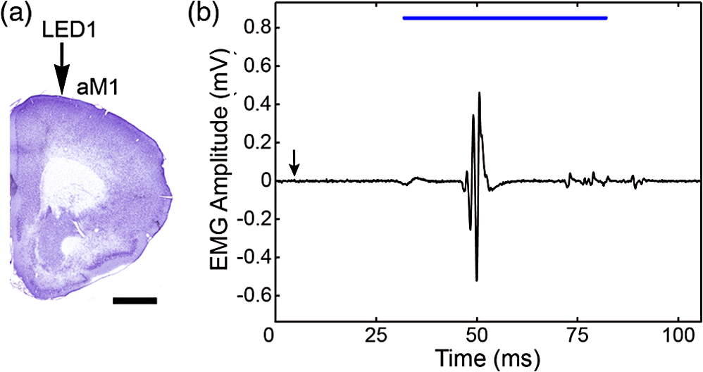 To confirm wireless optogenetic stimulation of a freely moving mouse, we mounted an LED stimulator on the head of a Thy1-ChR2-YFP mouse [refer to Fig. 4(d)]. LED1, LED2, and LED3 were fixed on the right side of the skull corresponding to aM1, mlV2, and pM1/S1, respectively [Fig. 3(d), see Sec. 2.4]. When LED1 was activated (frequency, 10 Hz; duration, 50 ms; interval, 2 s), the mouse clearly turned its head to the left. By contrast, when LED2 and LED3 generated photopulses, no obvious changes in motor behavior were observed. These behaviors were reproduced in other animals. We conclude that the light intensity delivered by the LED stimulator was sufficient to stimulate ChR2-expressing neurons through the unthinned skull. Next, two small LEDs were fixed on the skull over the aM1 of the right and left hemispheres [Fig. 4(c), right LED, left LED], and an LED stimulator was attached [Fig. 4(d)]. The photopulses presented to the right and left aM1 changed the moving direction of a freely moving Thy1-ChR2-YFP mouse to the left and right, respectively [Figs. 4(a) and 4(b); Video 1]. Consequently, the wireless LED-stimulating system was successfully used to control the motor behavior of a freely moving Thy1-ChR2-YFP mouse. 3.3.Application of Multidevice StimulationWe used 8-bit binary codes to discriminate among channels (e.g., Ch.3, 00001111) in the wireless LED-stimulating system (Fig. 2), allowing up to 256 codes. For multidevice applications, individual LED stimulators can be programmed to recognize unique 8-bit binary codes. For instance, we modified one LED stimulator to recognize the 8-bit binary codes of Ch.5 to Ch.8 (Ch.5, 00011101, LED5; Ch.6, 00011110, LED6; Ch.7, 00011111, LED7; Ch.8, 00000100, LED5 and LED6; LED-stimulator No. 2, Video 2) and used it with another LED stimulator that recognized Ch.1 to Ch.4 (Ch.1, 00001101, LED1; Ch.2, 00001110, LED2; Ch.3, 00001111, LED3; Ch.4, 00011100, LED1 and LED2; LED stimulator No. 1, Video 2) in the same field. Each channel of the two LED stimulators could individually be controlled by the IR photopulses of Ch.1 to Ch.8 without crosstalk. Furthermore, to establish IR transmission at multiple frequency bands, we adapted the IR transmitter and LED stimulator for carrier frequencies of 30, 38, and 56 kHz. The modified LED stimulators discriminated between 30- and 56-kHz IR photopulses, but 38-kHz transmission was received by both 30- and 56-kHz devices. Therefore, carrier frequencies of 30 and 56 kHz can be used for multiband IR transmission (Video 3). Consequently, we could use multiple LED stimulators for photostimulation of animals in the same experimental arena at the same time. Video 2Use of multiple LED stimulators in the same field. LED stimulator No. 1 was programmed to accept IR photopulses coding Ch.1 to Ch.4. Ch.1, Ch.2, and Ch.3 drove green, yellow, and blue small LEDs, respectively. LED stimulator No.2 was programmed to accept IR photopulses coding Ch.5 to Ch.8. A learning remote controller learned IR photopulses of Ch.1 to Ch.8 at the buttons with the corresponding numbers. LED stimulator No. 1 and No. 2 distinguished IR photopulses and individually generated photopulses according to the number(s) of the learning remote controller. (QuickTime, 8.6 MB) [URL: http://dx.doi.org/10.1117/1.NPh.1.1.011002.2]. 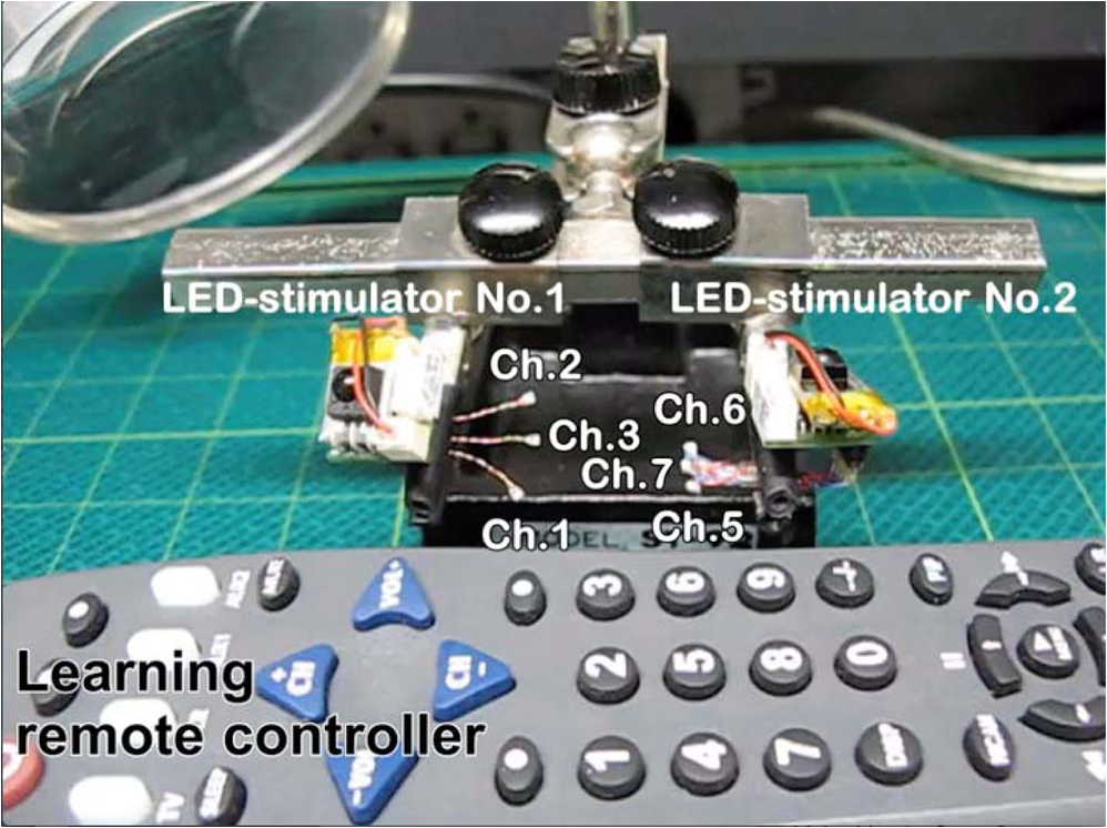 Video 3Use of multiband LED stimulators in the same field. The IR transmitters and LED stimulators were adapted to 30-kHz (labeled 30 kHz) and 56-kHz IR photopulses (labeled 56 kHz). A shell-type LED placed on the IR stimulator flashed simultaneously with a TTL trigger signal input into the IR stimulator. (QuickTime, 8.7 MB) [URL: http://dx.doi.org/10.1117/1.NPh.1.1.011002.3]. 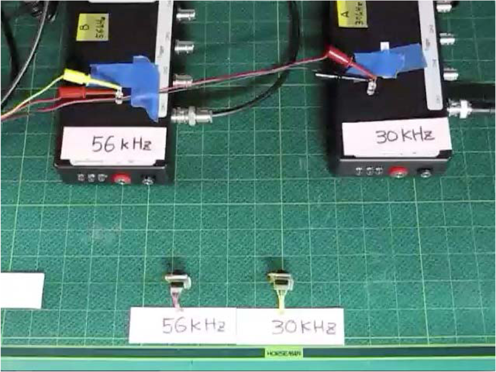 Finally, the output portion of the LED stimulator can be further engineered. For intracranial stimulation, a small LED could be attached to an optical fiber that had a diameter of 0.5 mm (Video 4). The light intensity at the tip of the optical fiber was . Alternatively, it was possible to insert a small LED () into a glass pipette that had an external diameter of 1.5 mm and internal diameter of 0.86 mm (Video 5). A small LED attached to an optical fiber and a small LED enclosed in a glass pipette can be used to lead photopulses into a deep area of a brain. Moreover, small LEDs that emit at many wavelengths (e.g., blue, 470 nm; green, 525 nm; yellow, 590 nm; red, 630 nm) are commercially available and the LED color can be adapted to various optogenetic molecules (Video 2). Notably, the LED stimulator can drive an RGB multicolor LED using three output channels (Video 6). An RGB multicolor LED may be able to stimulate step-function opsin (SFO) because the channel of SFO is opened by blue light and closed by green light.5,12,13 Video 4Small LEDs coupled to an optical fiber. The small LEDs were connected to the receptacles for LEDs of an LED stimulator (LED1 and LED2). (QuickTime, 0.5 MB) [URL: http://dx.doi.org/10.1117/1.NPh.1.1.011002.4]. 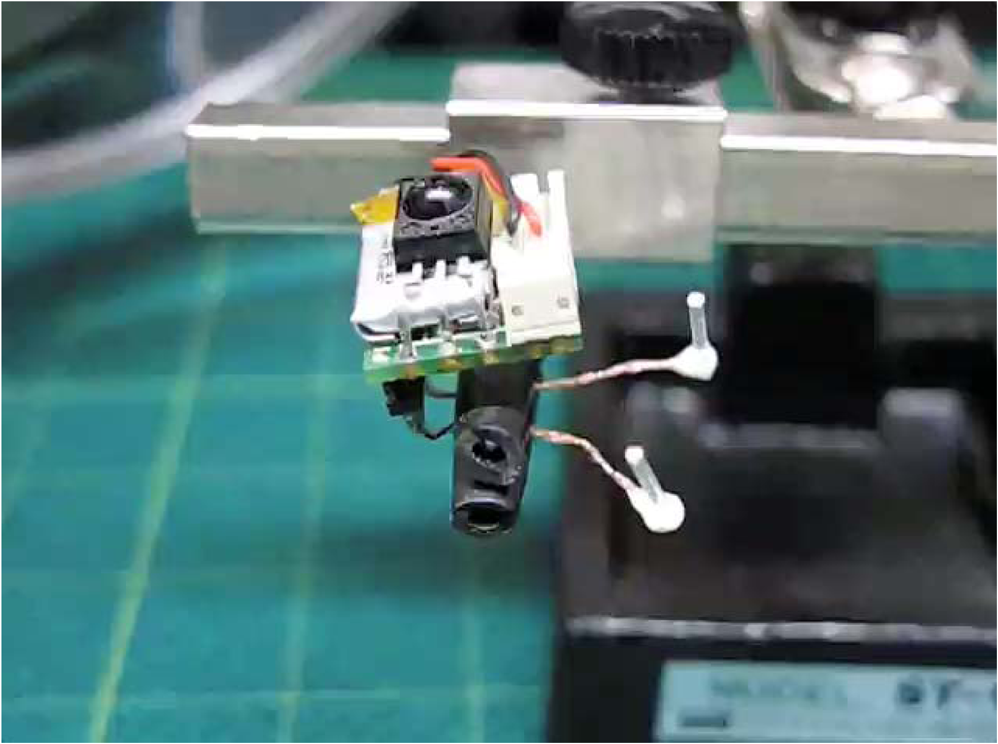 Video 5A small LED enclosed in a glass pipette. (QuickTime, 0.3 MB) [URL: http://dx.doi.org/10.1117/1.NPh.1.1.011002.5]. 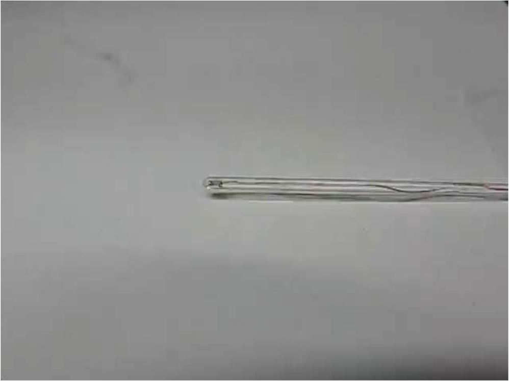 Video 6RGB LED driven by an LED stimulator. The RGB LED has four anode pins for red, green, and blue LEDs, and a cathode. The anodes for blue, red, and green LEDs were connected to the anodes of LED1, LED2, and LED3 of the LED stimulator, respectively. The cathode of the RGB LED was connected to the cathode of the LED stimulator. The LED stimulator generated photopulses from LED1 (blue), LED2 (red), LED3 (green), and LED1 and LED2 (purple, mixture of blue and red) in that order. (QuickTime, 0.5 MB) [URL: http://dx.doi.org/10.1117/1.NPh.1.1.011002.6].  4.DiscussionWe developed a new generation of wireless LED-stimulating system by improving our previous version.6 The improvements include (1) miniaturization, (2) multicode, (3) multiband, (4) multiple LEDs, and (5) programmable pulse patterns. Compared with the first-generation device,6 the present device was smaller in both dimensions and weight ( and 2.4 g, respectively), resulting in a reduction of inertia. Indeed, no obvious sign of head movement compromise was seen in the implanted mice. The improved system used 8-bit serial pulse coding to activate the LED stimulator, allowing generation of multiple stimulus patterns (up to 256 codes) in multiple devices. Furthermore, we implemented multiband IR transmission for truly concurrent activation of multiple devices. Finally, the programmable microcontroller enables definition of arbitrary digital stimulus patterns with multiple LEDs, which can be changed according to experimental design. The LED stimulator took to initiate LED emission after TTL trigger input into the IR transmitter [Fig. 7(b), arrow], which is as long as the length of the IR transmission code (Fig. 2). By contrast, the head-mounted device of our previous system emits a photopulse with a delay of 170 to 180 μs.6 In the event that a delay of 27.2 ms will be a problem in studying animals’ behavior, the leader code and coding bit length could be made shorter. For example, the delay is reduced to when four-bit binary codes are used, at the expense of reducing to 16 codes for IR reception. Our wireless LED-stimulating system is compared with other available wireless LED-stimulating systems in Table 1. In addition to its compact size, our wireless LED-stimulating system carries the advantage of having 256 reception codes. Therefore, multiple LED stimulators (up to 64) can be individually used in the same field. Moreover, our system does not need an external pulse generator to generate LED pulse patterns because of microcontroller programming, as also implemented in the system developed by Wentz et al.7 One potential advantage of local pulse generation is in a situation in which the animal becomes inaccessible to incoming IR signals after receiving the trigger (for instance, when a mouse mounted with an LED stimulator dives into bedding). In that case, our LED stimulator continues to generate a preprogrammed train of pulses, unlike other devices using IR transmission. We used a rechargeable battery as the power source of the LED stimulator. The power limitation of the rechargeable battery becomes a problem when performing tests of long duration. If a battery with large capacity is used, the driving time of the LED stimulator is extended but the weight of the battery is increased. The weight increase of the head-mounted device is a critical problem for a small animal. It is easy to replace the LED stimulator with a spent battery with another LED stimulator attached to a charged battery. Therefore, it seems possible to extend the duration of a test simply by replacement of the LED stimulator. Several studies report head-mounted LED stimulators driven by wireless energy transmission,7,14,15 which overcomes the problem of battery capacity. We employ IR signals to communicate with the head-mounted LED stimulator, but Wentz et al.7 used radio frequency (RF) communication to control their head-mounted LED stimulator. RF systems are powerful wireless systems, but IR systems have the advantage of being simpler than RF ones. We do not need many electronic components to develop the IR communication, and as a result, we can reduce the production cost and weight of the head-mounted device. In addition, the power consumption of an IR system is generally lower than that of an RF one. This is advantageous for using a battery. Table 1Comparison of wireless light-emitting diode (LED)-stimulating systems.
Our system may be useful for experiments in complex environments with multiple animals and may act as a physiological conditioning factor to stimulate a restricted neuronal circuit in freely moving animals. AcknowledgmentsWe thank Dr. G. Augustine for permission to use Thy1-ChR2-YFP mice. This work was supported by JSPS KAKENHI Grant Number 25430008 and also by the Funding Program for World-Leading Innovative R&D on Science and Technology (FIRST Program). ReferencesH. Yawoet al.,
“Optogenetic manipulation of neural and non-neural functions,”
Dev., Growth Differ., 55
(4), 474
–490
(2013). http://dx.doi.org/10.1111/dgd.12053 DGDFA5 0012-1592 Google Scholar
J. Mattiset al.,
“Principles for applying optogenetic tools derived from direct comparative analysis of microbial opsins,”
Nat. Methods, 9
(2), 159
–172
(2011). http://dx.doi.org/10.1038/nmeth.1808 1548-7091 Google Scholar
V. Gradinaruet al.,
“Targeting and readout strategies for fast optical neural control in vitro and in vivo,”
J. Neurosci., 27
(52), 14231
–14238
(2007). http://dx.doi.org/10.1523/JNEUROSCI.3578-07.2007 JNRSDS 0270-6474 Google Scholar
F. Matyaset al.,
“Motor control by sensory cortex,”
Science, 330
(6008), 1240
–1243
(2010). http://dx.doi.org/10.1126/science.1195797 SCIEAS 0036-8075 Google Scholar
O. Yizharet al.,
“Neocortical excitation/inhibition balance in information processing and social dysfunction,”
Nature, 477
(7363), 171
–178
(2011). http://dx.doi.org/10.1038/nature10360 NATUAS 0028-0836 Google Scholar
Y. Iwaiet al.,
“A simple head-mountable LED device for chronic stimulation of optogenetic molecules in freely moving mice,”
Neurosci. Res., 70
(1), 124
–127
(2011). http://dx.doi.org/10.1016/j.neures.2011.01.007 NERADN 0168-0102 Google Scholar
C. T. Wentzet al.,
“A wirelessly powered and controlled device for optical neural control of freely-behaving animals,”
J. Neural Eng., 8
(4), 046021
(2011). http://dx.doi.org/10.1088/1741-2560/8/4/046021 1741-2560 Google Scholar
B. R. Arenkielet al.,
“In vivo light-induced activation of neural circuitry in transgenic mice expressing channelrhodopsin-2,”
Neuron, 54
(2), 205
–218
(2007). http://dx.doi.org/10.1016/j.neuron.2007.03.005 NERNET 0896-6273 Google Scholar
H. Wanget al.,
“High-speed mapping of synaptic connectivity using photostimulation in channelrhodopsin-2 transgenic mice,”
Proc. Natl. Acad. Sci. U. S. A., 104
(19), 8143
–8148
(2007). http://dx.doi.org/10.1073/pnas.0700384104 PNASA6 0027-8424 Google Scholar
R. Hiraet al.,
“Transcranial optogenetic stimulation for functional mapping of the motor cortex,”
J. Neurosci. Methods, 179
(2), 258
–263
(2009). http://dx.doi.org/10.1016/j.jneumeth.2009.02.001 JNMEDT 0165-0270 Google Scholar
J. Y. Lin,
“A user’s guide to channelrhodopsin variants: features, limitations and future developments,”
Exp. Physiol., 96
(1), 19
–25
(2011). http://dx.doi.org/10.1113/expphysiol.2009.051961 EXPHEZ 0958-0670 Google Scholar
A. Berndtet al.,
“Bi-stable neural state switches,”
Nat. Neurosci., 12
(2), 229
–234
(2009). http://dx.doi.org/10.1038/nn.2247 NANEFN 1097-6256 Google Scholar
C. Bamannet al.,
“Structural guidance of the photocycle of channelrhodopsin-2 by an interhelical hydrogen bond,”
Biochemistry, 49
(2), 267
–278
(2010). http://dx.doi.org/10.1021/bi901634p MIRBD9 0144-0578 Google Scholar
J. G. McCallet al.,
“Fabrication and application of flexible, multimodal light-emitting devices for wireless optogenetics,”
Nat. Protoc., 8
(12), 2413
–2428
(2013). http://dx.doi.org/10.1038/nprot.2013.158 NPARDW 1754-2189 Google Scholar
A. J. Yehet al.,
“Wirelessly powering miniature implants for optogenetic stimulation,”
Appl. Phys. Lett., 103
(16), 163701
(2013). http://dx.doi.org/10.1063/1.4825272 APPLAB 0003-6951 Google Scholar
|


